Every drawing I have made or cleaned up for Cedarhaus, with its status in brackets. Confirmed means it matches what is being built; Proposed means it is the plan but not yet field-verified; Needs verification means a later ruling changed something on it; Superseded means a newer drawing replaces it and it is kept for the history. Camera and access-control positions are withheld: security drops appear as SEC-nn, and the placement, conduit, and door-hub drawings stay off the site.
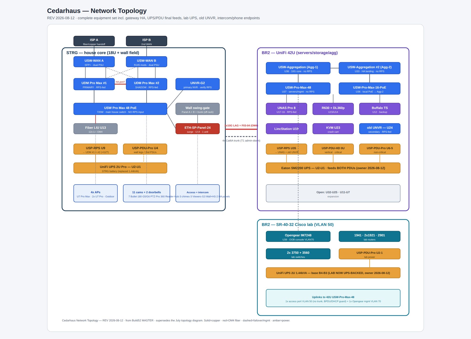
Network topology (rev 2026-08-12) [Confirmed]
Full equipment set: dual ISP feeds into the WAN pair, the UDM Pro Max HA gateway pair, the STRG core switch and surge panel, the BR2 42U aggregation stack, and the Cisco lab on the swing-out. Cameras and access devices appear as counts only. Full size
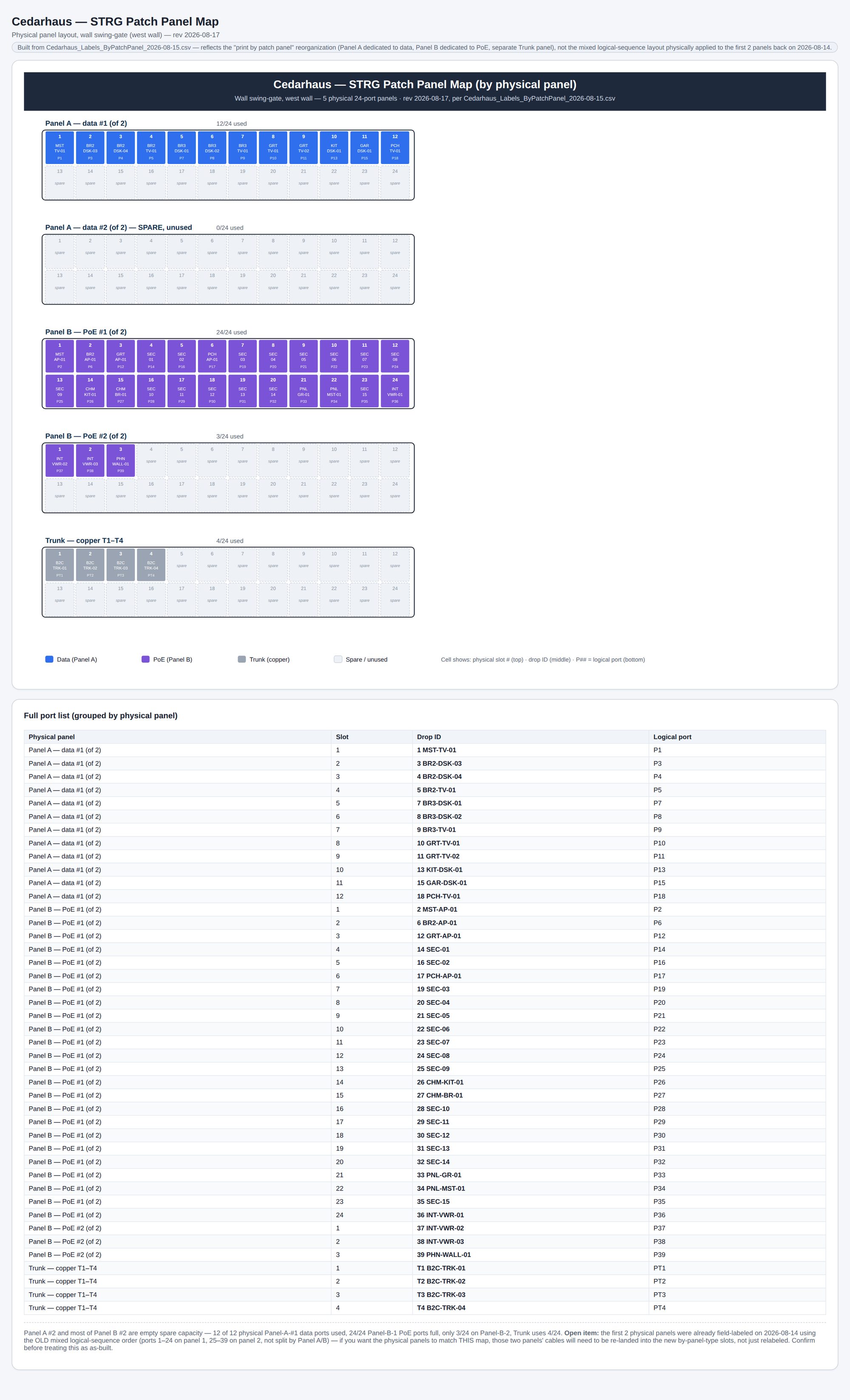
STRG patch panel map by physical panel (rev 2026-08-17) [Proposed]
Five 24-port panels on the wall swing-gate: Panel A data (12/24 used, second panel spare), Panel B PoE (24/24 + 3/24), and the copper trunk T1–T4. Each cell shows physical slot, drop ID, and logical port. Security drops are labelled SEC-01..15 on this public copy. Open item: the first two panels were field-labelled in the old logical order and still need to be re-landed to match this map. Full size
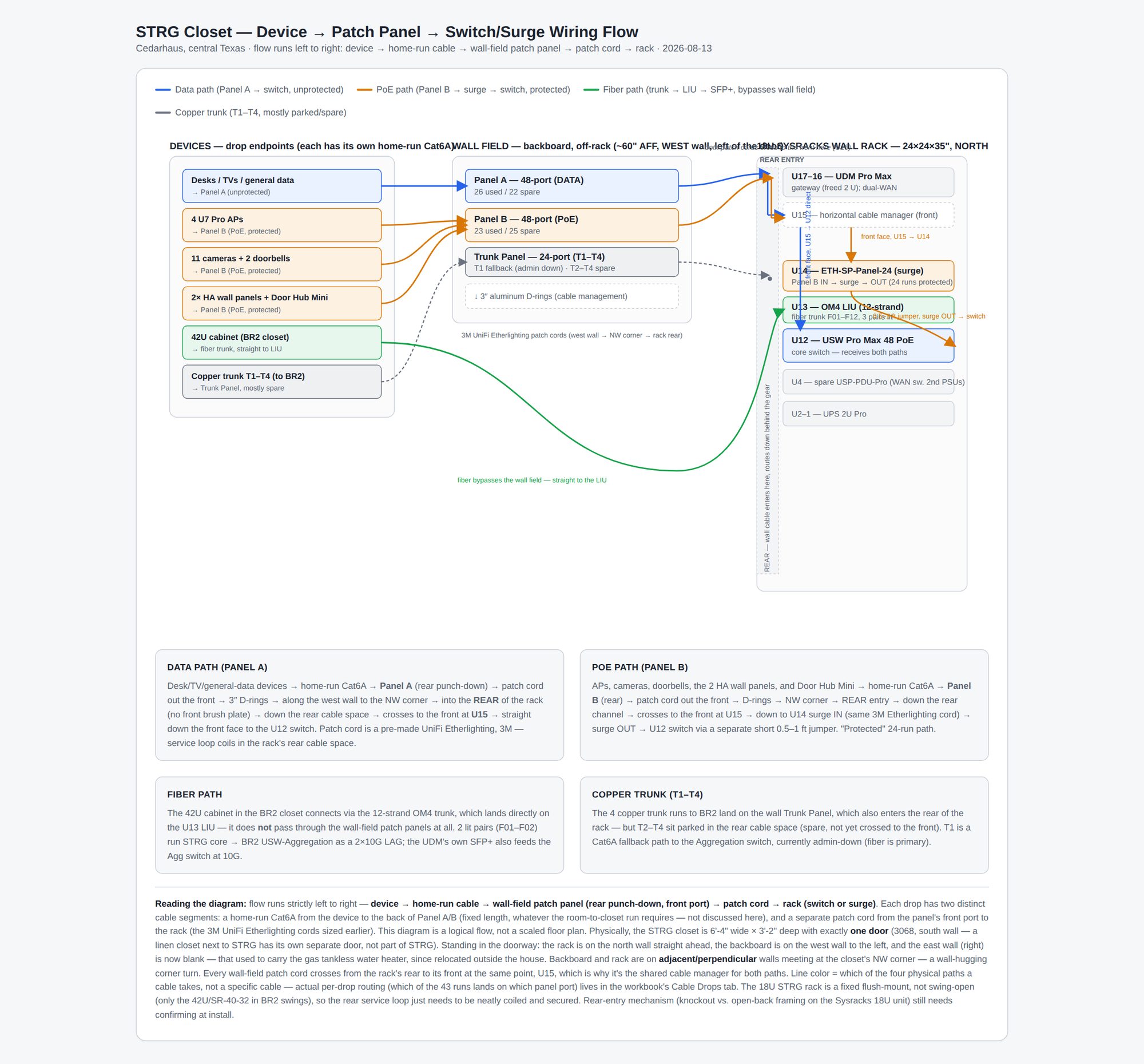
Left to right: device, home-run Cat6A, wall-field patch panel (Panel A data / Panel B PoE / trunk panel), patch cord, then rack — surge panel for protected PoE runs, straight to the switch for the rest. Fiber trunk bypasses the wall field to the LIU. Drawn before the west-wall rack ruling and before the water heater moved outside; the wall-field logic still holds. Full size
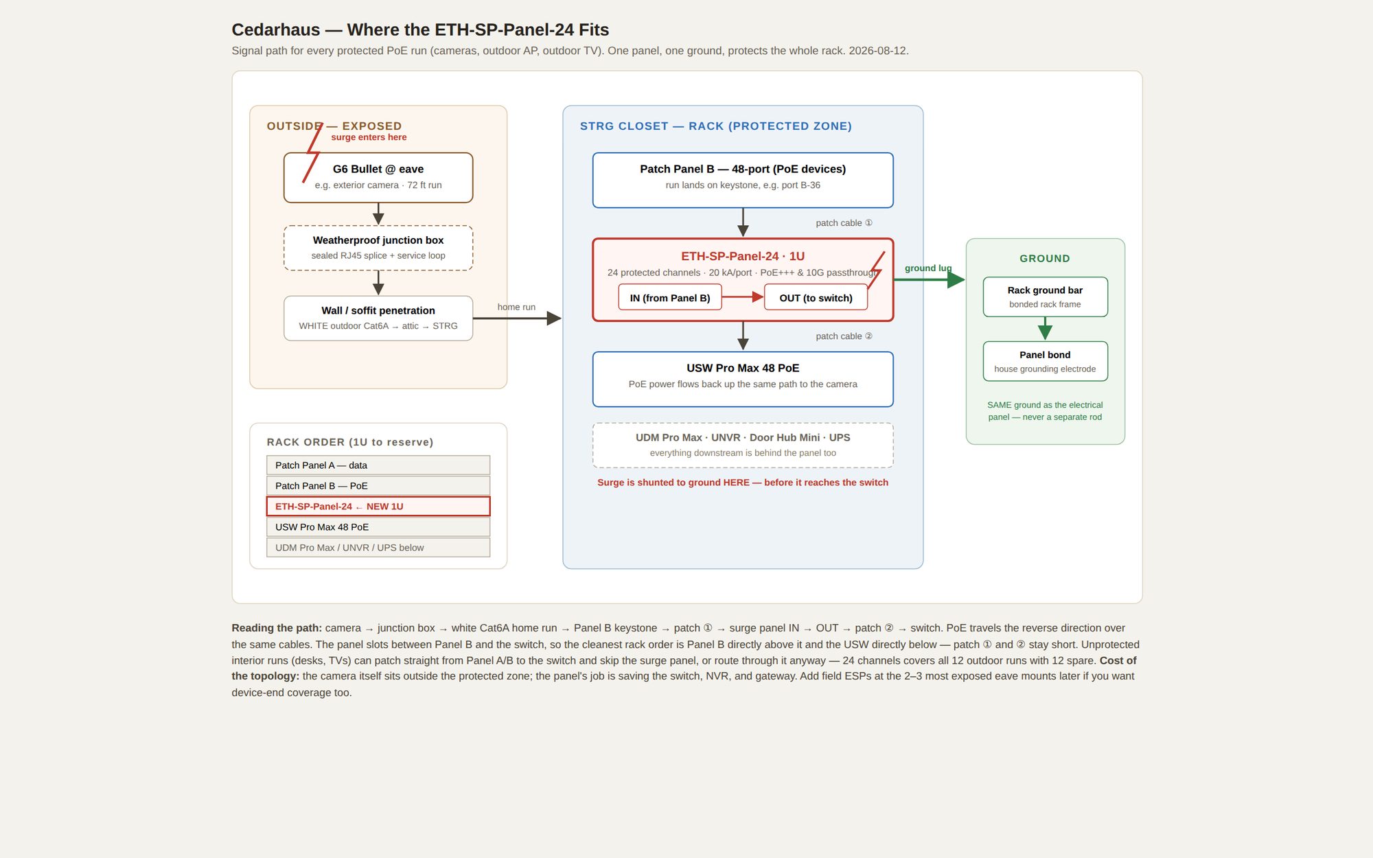
Surge panel signal path (rev 2026-08-12) [Confirmed]
How every protected PoE run flows: device, junction box, home-run, Panel B keystone, patch cord, surge panel IN/OUT, second patch cord, switch. PoE rides back the same path. 24 channels cover the 12 outdoor runs with 12 spare. Full size
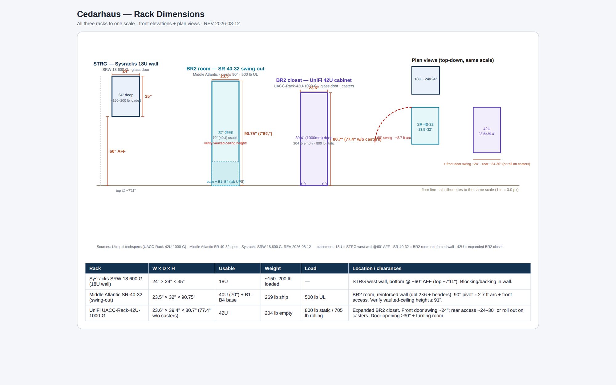
Rack dimensions and clearances (rev 2026-08-12) [Confirmed]
Outside dimensions, swing arcs, and front/rear service clearances for the three racks — the sheet the closet-framing conversation with the builder ran off. Full size
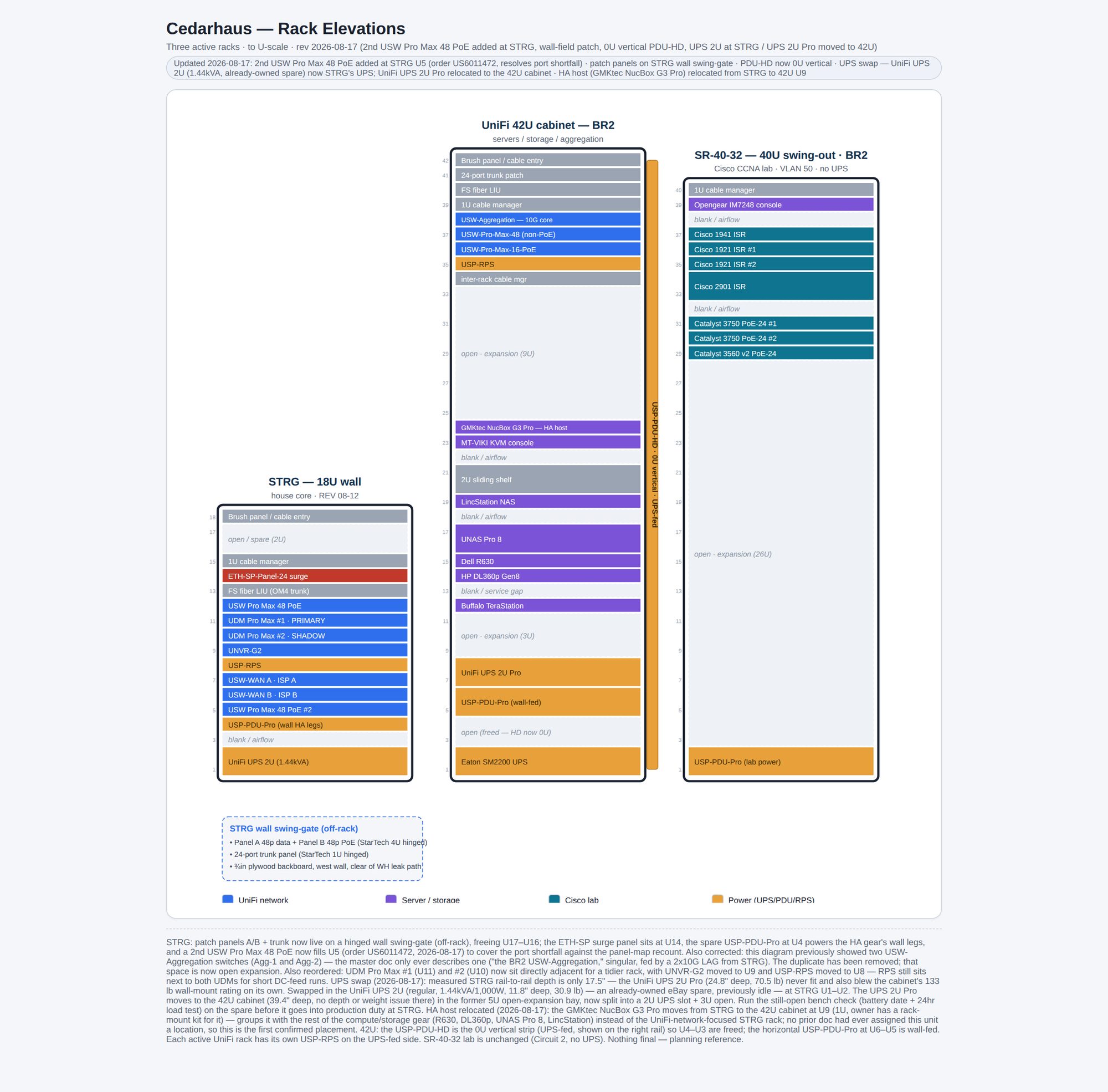
Rack elevations (rev 2026-08-12) [Superseded]
Front elevations as drawn on 08-12. Superseded by the 08-17 U-maps, which are what the Command Center rack explorer renders (RPS at U8, WAN pair at U6–U7, UPS at U1–U2). Full size
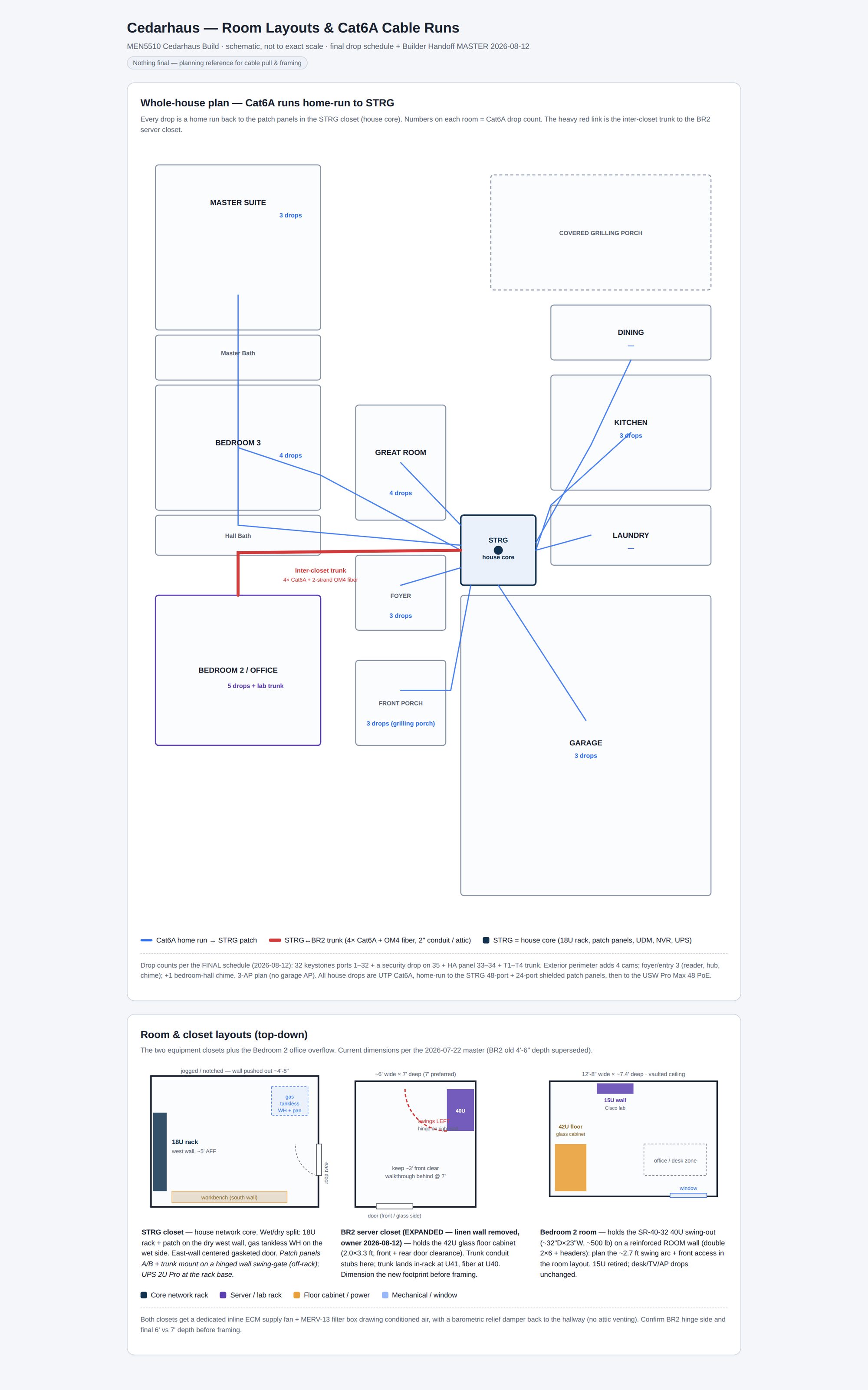
Room layouts and Cat6A home runs (rev 2026-08-12) [Superseded]
Not-to-scale schematic of each room's drop count and home run to STRG, the inter-closet trunk, and top-down closet layouts. Superseded details: 3-AP plan (now 4), water heater in STRG (now gas tankless outside), 15U wall rack (retired for the SR-40-32 swing-out). Drop counts predate the 53-drop ruling. Full size
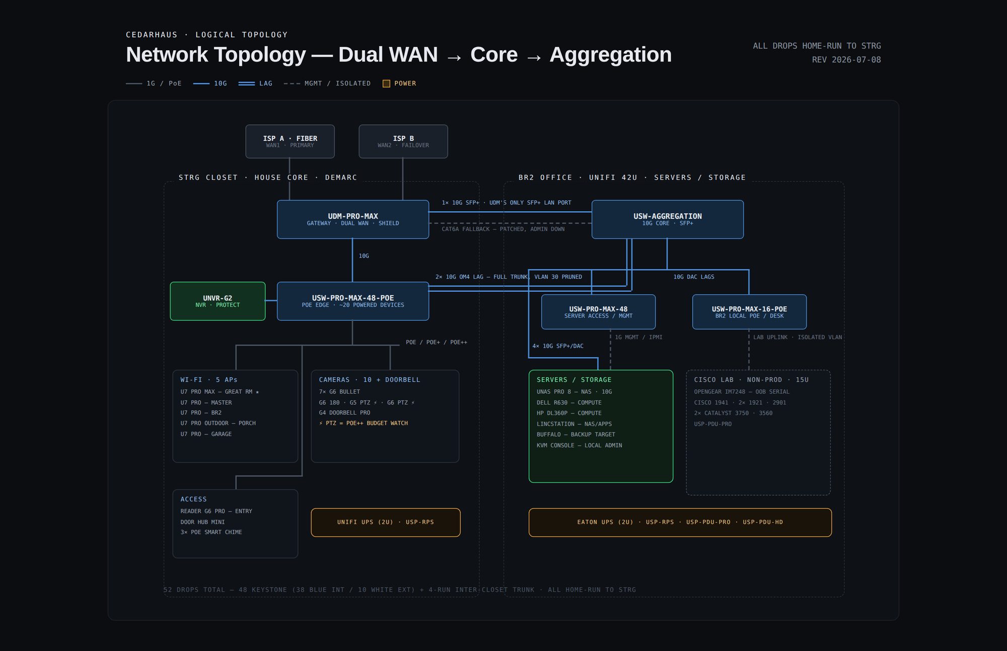
Logical topology (rev 2026-07-08) [Superseded]
The July logical view: dual WAN into a single UDM Pro Max, core PoE switch, aggregation in BR2. Superseded by the 08-12 topology but kept because it explains the original layer split. Full size
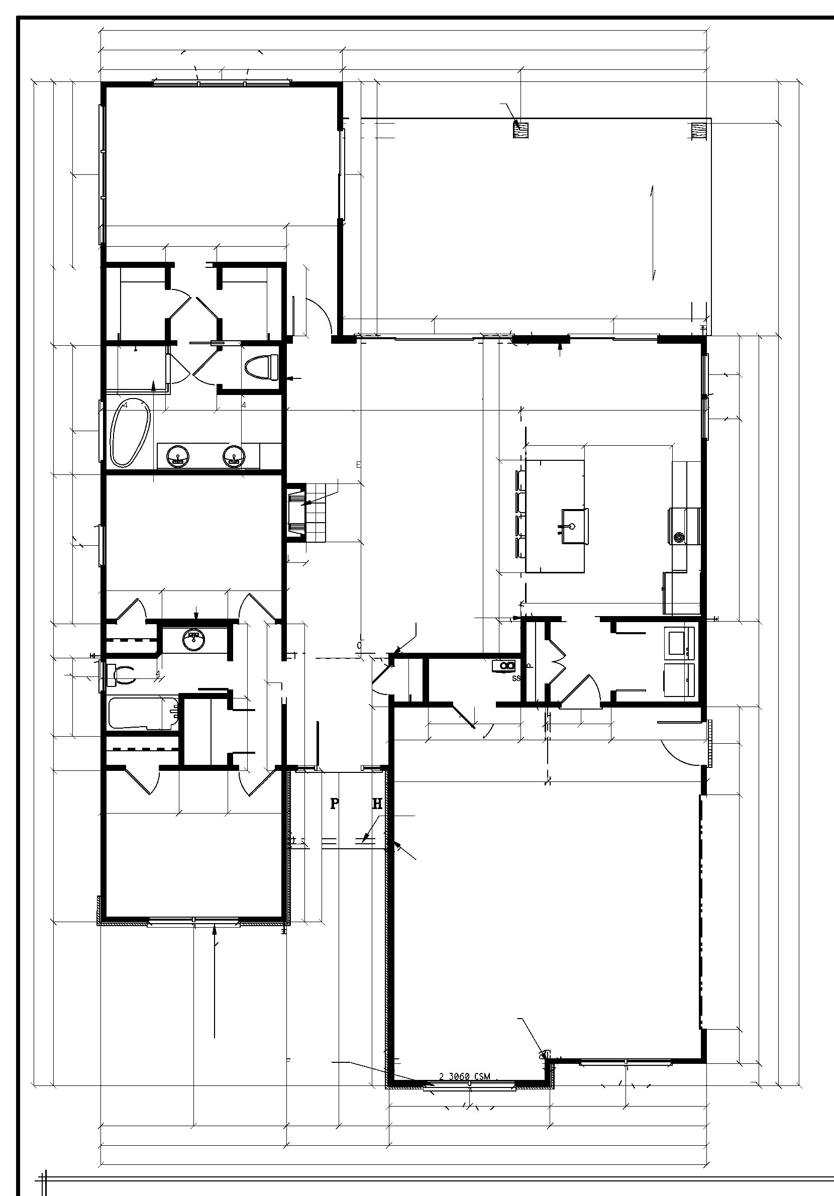
Architectural floor plan (walls only) [Confirmed]
The MEN5510 plan with all text and dimensions stripped. This is the base drawing under the Command Center floor plan; room polygons traced from it are marked Estimated until surveyed. Full size
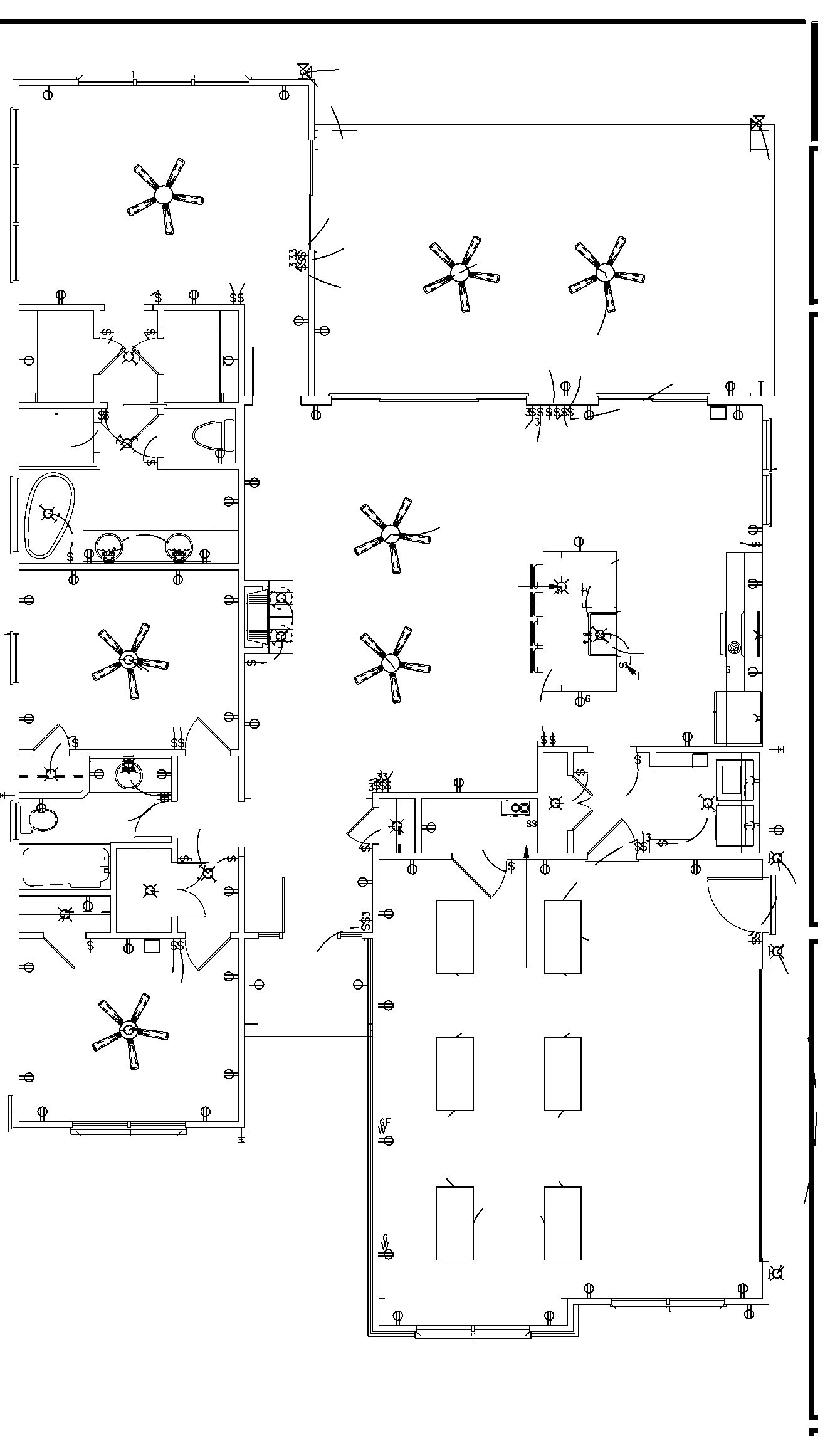
Electrical floor plan (text removed) [Confirmed]
The builder's electrical sheet with text removed — useful for seeing where receptacles and switch legs land relative to the low-voltage drops. Full size
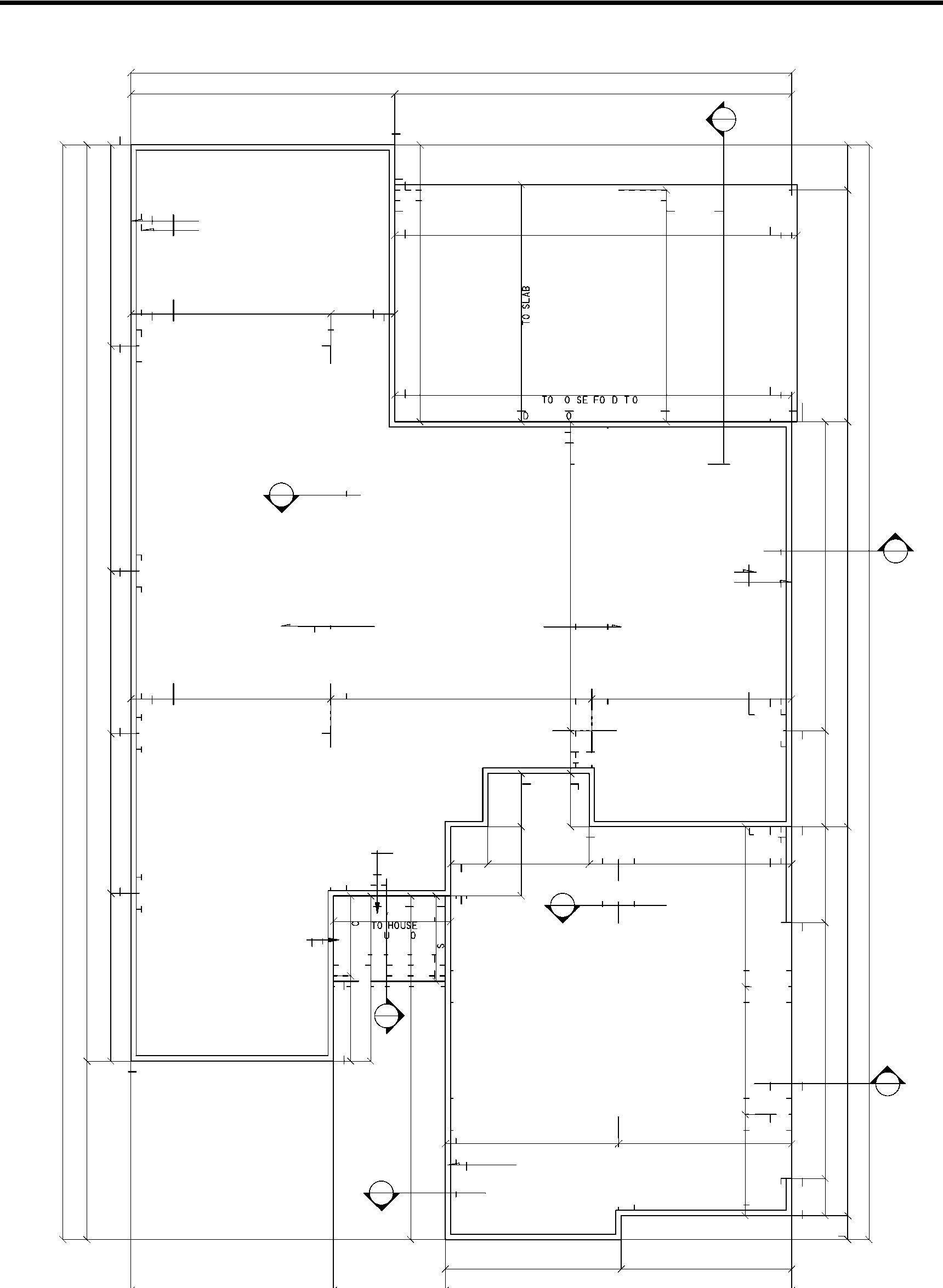
Foundation plan (text removed) [Confirmed]
Slab and beam layout with text removed. Referenced when planning the under-slab conduit stubs to the STRG and BR2 closets. Full size